Tension In Concrete - An Article
CONCRETE TENSION IN UNDERGROUND PRECAST STRUCTURES
By Gary K. Munkelt, PE
October 30, 2018
SYNOPSIS
Tension capacity in concrete is known to be much weaker than compression capacity and is seldom used without reinforcing steel bars when tension is required. A statement in the ACI 318 Structural Concrete Building Code suggests that for most conditions tension should be taken as zero (ACI Committee 318, 2014). There are conditions, however, where tension capacity is important. Cracking and diagonal shear limits involve tension. In the underground precast concrete industry thickness of walls and slabs need to be thin to reduce weight. One such product is the precast burial vault where a wall with short span is exposed to medium loads and resists load with only tension capacity of concrete. The discussion following will establish tension capacity values of concrete based on available test data. It also includes discussion of factor of safety as applied to poured-in-place concrete and underground precast concrete products.
INTRODUCTION
The ACI 318 Building Code is the guideline for general concrete design (ACI Committee 318, 2014). It is written to cover the worst-case conditions that may occur during construction with poor quality control when concrete is poured-in-place. The formulas include a Factor of Safety larger than would be required when a rigorous “quality control” program is in place during construction.
The precast concrete industry has mastered quality control out of necessity to produce a product much more reliable than the poured-in-place version. To be competitive, precast products must be removed from forms without cracks when the concrete is only 24 hours old. This requires high-strength concrete and good curing systems. Tension for products produced in this manner can be considered more reliable than poured-in-place concrete to justify a lower Factor of Safety.
Currently, the code recommends a low-tension coefficient for worst-case situations and a higher tension coefficient for situations that include “beneficial effects”. The lower value creates a higher Factor of Safety. Data and discussion in this paper demonstrate that designs for underground precast concrete products produced with high-strength concrete and certified quality control procedures has the added “beneficial effect” to warrant use of the larger value for calculating allowable shear strength tension capacity ( ). Applying the higher value from the code will still result in a Factor of Safety acceptable to protect the safety of the public.
METHODS FOR DETERMINING TENSILE STRENGTH OF CONCRETE
The concrete industry has struggled since the beginning of the 20th century to determine a reliable method for predicting the tensile strength of concrete. Three methods have been used to provide data. Two methods are described in American Society of Testing and Materials (ASTM) standards. The third method is not covered by an ASTM standard. The three methods for creating data are:
- PURE TENSION TESTING
- FLEXURAL TENSION TESTING
- SPLIT CYLINDER TESTING
Data from these test methods can be useful when an engineer needs to consider conditions in the design of beams and round structures.
EXAMPLE OF BEAM OR WALL:
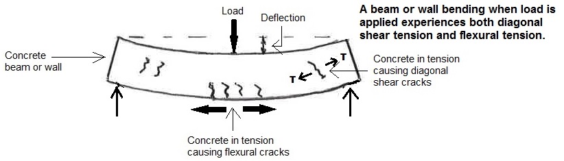
Figure 1 - Side View of Beam Exposed to Load
EXAMPLE OF ROUND STRUCTURE:
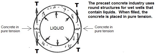
Figure 2 - Plan View of Wet Well
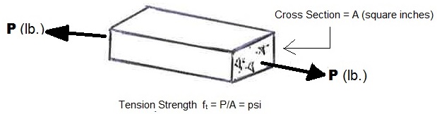
Figure 3 - Testing a Concrete Specimen
ACI document 224.2R states, “Because of difficulties associated with applying a pure tensile force to a plain concrete specimen, there are no standard tests for direct tension” (ACI Committee 224, 1992, p. 3). The data supplied by the Portland Cement Association, however, are useful because they provide a relationship between compression strength and tension capacity.
| Compressive Strength (f'c) | x | Coefficient | = | Tension Strength (f't) |
|---|---|---|---|---|
| 3000 psi | x | 9.2% | = | 275 psi |
| 5000 psi | x | 8.0% | = | 400 psi |
FLEXURAL TENSION data can be created using ASTM Standard C78. The Standard, originally created in 1930, is titled “Standard Test Method for Flexural Strength of Concrete (Using Simple Beam with Third Point Loading)” (ASTM Committee C 09, 2018). It is used to determine flexural strength of a plain concrete beam. The results have been used to confirm mix designs and quality control of slab and pavement construction.
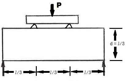
Figure 4 - Side View of Test Beam
This test method consists of applying a load to a rectangular beam until it breaks. The maximum applied load (P) is used in a formula to create the “theoretical maximum tensile strength,” also called the “modulus of rupture”. It is useful to designers of flexural beams by providing an indicator of when plain concrete will crack.
Flexural Tension = Modulus of Rupture = R (psi) = Pl ÷ bd2
Where P = load recorded by testing machine when failure occurred (lb-ft)
l = span length (in.)
b = width of beam (in.)
d = depth of beam (in.)
To distinguish flexural tension from pure tension, consider using terminology:
PURE TENSION - f 't
FLEXURAL TENSION - f 'r (modulus of rupture)
Because this formula is based on the assumption that concrete is an elastic material and the bending stress is localized in the outermost fibers, f'r is apt to be larger than f't. Test data from this method will be useful when doing calculations involving flexure in beams or slabs, not pure tension as in round structures containing liquids.
| Compressive Strength (f'c) | x | Coefficient | = | Tension Strength (f't) |
|---|---|---|---|---|
| 3000 psi | x | 16.2% | = | 485 psi |
| 5000 psi | x | 13.5% | = | 675 psi |
Note. Data from ACI Committee 224.2R, 1993; Price, 1951
“Splitting tensile strength is generally greater than direct tensile strength and lower than flexural strength (modulus of rupture).” (p. 1).
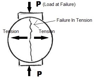
Figure 5 - Section View of Cylinder
The test method uses the same-shaped cylinder normally made to test for compressive strength of the concrete. Instead of applying compression to the ends of the cylinder, it is applied to the longitudinal axis. Tensile strength of the concrete is calculated from the formula:
Splitting Tensile Strength T = 2P ÷ πld = f 'sp (psi)
Where P = maximum applied load indicated by the testing machine (lb.)
l = length (inches) of the specimen
d = diameter (inches) of the specimen
A reasonable estimate for split cylinder strength (f 'sp) values is suggested by Winter (1964).
Low-strength sand-gravel concretes result in f 'sp = 7 √f 'c
High-strength sand-gravel concretes result in f 'sp = 6 √f 'c
| Example: For Compressive Strength of Concrete | Split Cylinder Tension f 'sp |
|---|---|
| 3000 psi | f 'sp = 7√3000 = 383 psi |
| 5000 psi | f 'sp = 6√5000 = 424 psi |
Note: Data from Winter, 1964
PURE TENSION - f 't
FLEXURAL TENSION - f 'r (modulus of rupture)
SPLIT CYLINDER TENSION - f 'sp
POURED-IN-PLACE CONCRETE
Engineers use the formulas recommended by ACI 318 (ACI Committee 318, 2014) for shear strength when designing concrete structures. These formulas have been successful for many years in the design of poured-in-place concrete where quality control practices are not always utilized. The formulas provide a Factor of Safety to cover the unanticipated conditions that can happen when quality control procedures are absent.
A Factor of Safety can be obtained by comparing “ultimate test results” with recommended ACI 318 formulas. Chapter 11 covers shear strength of concrete (Vc for members subject to shear and flexure only) with a simplified formula and a more detailed formula. The second formula considers beneficial effects for percent of reinforcing steel (p), ultimate moment (Mu), and ultimate shear (Vu).
A look at Factors of Safety provided by these values indicates that they are very conservative. This is necessary for concrete installed without quality control in place. Consider the concrete used in many poured-in-place projects:
ACI 318 SIMPLIFIED FORMULA 11-3 (used as default when details not available).
Vc = 2√f 'c x b x d where 2√f 'c = coefficient
For pure tension: Compare coefficient 2√3000 = 110 psi to split cylinder data f 'sp = 383 psi Factor of Safety = 383 ÷ 110 = 3.5
ACI 318 DETAILED FORMULA 11-5 (used when beneficial effects are known).
Vc = [1.9√f 'c + 2500p(Vu x d ÷ Mu)]b x d
But not greater than 3.5√f 'c x b x d where 3.5√f 'c = coefficient
For pure tension: Compare coefficient 3.5√3000 = 192 psi to split cylinder data f 'sp = 383 psi
Factor of Safety = 383 ÷ 192 = 2.0
UNDERGROUND PRECAST CONCRETE PRODUCTS
The precast concrete industry has for 50 years produced products for underground projects. Precast wet wells, utility vaults, septic tanks and burial vaults are some of the products in use today. They are made in manufacturing plants with high strength concrete and sophisticated quality control procedures.
Quality control is provided out of necessity because the precast manufacturer needs to pour concrete one day and remove the product from the form in 24 hours. If concrete is not strong at that time, removal of the product from the form will result in rejection due to failure or cracks. Precast manufacturers do not stay in business with an abundance of failures.
Quality control in manufacturing plants is applied in two ways. One way is by adhering to a “certified plant” inspection program provided by a third party. This is a program executed by the National Precast Concrete Association (NPCA) and the Prestressed Concrete Institute (PCI). It includes written procedures and unscheduled inspections by the third party.
The second way is automatic since the precast product (unlike poured-in-place concrete) must be removed from the form, transported by forklift and truck and installed at the jobsite. A weak product will crack or fail during this process.
The “ultimate tension test results” compared to ACI 318 formulas can be used to establish a factor of safety for the quality control produced precast product:
ACI 318 SIMPLIFIED FORMULA 11-3
Vc = 2√f 'c x b x d where 2√f 'c = coefficient
For pure tension: Compare coefficient 2√5000 = 141 psi to split cylinder data 6√5000 = f 'sp = 424 psi Factor of Safety = 424 ÷ 247 = 1.7
ACI 318 DETAILED FORMULA 11-5
Vc = [1.9√f 'c + 2500p(Vu x d ÷ Mu)]b x d
But not greater than 3.5√f 'c x b x d where 3.5√f 'c = coefficient
For pure tension: Compare coefficient 3.5√5000 = 247 psi to split cylinder data 6√5000 = f 'sp = 424 psi
Factor of Safety = 424 ÷ 247 = 1.7
CONCLUSION
Engineers unfamiliar with these Factors of Safety will apply the conservative coefficient of to precast concrete product designs. Table 4 suggests that the less conservative coefficient in the formula can be used for these products without jeopardizing the safety of the product or the public. This is all possible because of elaborate quality control procedures used in the precast manufacturing plants.
|
ACI Formula 11.3 2√f 'c |
ACI Formula 11.5 3.5√f 'c |
|
|---|---|---|
|
p.i.p Concrete |
3.5 | 2.0* |
|
Precast Concrete |
3.0 | 1.7* |
* The lower factor of safety of 1.7 for precast concrete vs. 2.0 for poured-in-place concrete is justified. The Factor of Safety = 2.0 is for the formula that is meant for lower quality control p.i.p construction whereas the Factor of Safety = 1.7 is for the high strength, quality control of precast concrete.
REFERENCES
ACI Committee 224. (1992). 224.2R - 92: Cracking of Concrete Members in Direct Tension. Farmington Hills: American Concrete Institute.
ACI Committee 318. (2014). 318-14: Building Code Requirements for Structural Concrete and Commentary. Farmington Hills: American Concrete Institute.
ASTM Committee C 09. (2017). ASTM C496/C496M - 17: Standard Test Method for Splitting Tensile Strength of Cylindrical Concrete Specimens. West Conshohocken, PA: American Society of Testing and Materials.
ASTM Committee C 09. (2018). C78/C78M - 18: Standard Test Method for Flexural Strength of Concrete (Using Simple Beam with Third-Point Loading) (Vol. 4.02). West Conshohocken, PA: American Society of Testing and Materials.
Price, W. H. (1951, February). Factors Influencing Concrete Strength. Journal of American Concrete, 47(2), 417-432.
Winter, G., & Nilson, A. H. (1964). Design of Concrete Structures [7th Ed. of the Work Originally Written by L.C. Urquhart & C.E. O'Rourke]. New York, NY: McGraw-Hill Book Company.
- 36899 reads
Members Of:


About Us
We are a small, flexible organization with over a century of combined engineering experience. Our unique combination of large-firm expertise coupled with small-firm personal attention allows Gary K. Munkelt & Associates to deliver structural engineering solutions tailored specifically to your business process. We treat every customer’s business as if it is our own.